This is default featured slide 1 title

Go to Blogger edit html and find these sentences.Now replace these sentences with your own descriptions.This theme is Bloggerized by Lasantha Bandara - Premiumbloggertemplates.com.

This is default featured slide 2 title

Go to Blogger edit html and find these sentences.Now replace these sentences with your own descriptions.This theme is Bloggerized by Lasantha Bandara - Premiumbloggertemplates.com.

This is default featured slide 3 title

Go to Blogger edit html and find these sentences.Now replace these sentences with your own descriptions.This theme is Bloggerized by Lasantha Bandara - Premiumbloggertemplates.com.

This is default featured slide 4 title

Go to Blogger edit html and find these sentences.Now replace these sentences with your own descriptions.This theme is Bloggerized by Lasantha Bandara - Premiumbloggertemplates.com.

This is default featured slide 5 title

Go to Blogger edit html and find these sentences.Now replace these sentences with your own descriptions.This theme is Bloggerized by Lasantha Bandara - Premiumbloggertemplates.com.

Saturday, May 15, 2021

What is piston/how piston work/piston's functions.

 PISTON

  A piston of an internal combustion engine is in the form of an inverted bucket shape and it is free to slide in the cylinder barrel. The gas tightness is secured by means of flexible piston rings, which are in the grooves of the piston. These grooves are cut in the upper part of the piston.

A piston of an internal combustion engine serves three functions:

1. It forms a moveable wall of the combustion chamber.

2. It transmits turning force to the crankshaft via the connecting rod.

3. It functions like a crosshead and transmits side thrust, which is due to the angularity of the connecting rods, to the cylinder walls.

The piston must possess the following qualities:

1. It must be strong enough to withstand high pressure caused due to the combustion of fuel.

2. It must be very light in weight to have minimum primary and secondary forces, which are caused due to the inertia forces of the reciprocating masses. A light piston permits higher speed of the crank.

3. The piston material must be a good conductor of heat so that detonation is suppressed, and higher compression ratio is possible to get fuel economy.

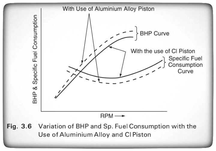
       It is interesting to know that an engine having a piston and cylinder head of aluminium alloy can be used at a compression ratio of 6.3 and it gives more power and fuel economy than similar engine having a cast iron piston and cylinder head at a compression ratio of 5.3 as shown in Fig. 3.6. This is due to the improved thermal efficiency, which is due to the thermal conductivity of aluminium alloy. Apart from the qualities mentioned previously, the piston must meet the following requirements:

1. The piston operation must not be noisy.

2. The piston must be of less coefficient of expansion.

     It has been found by experiments that the maximum temperature produced is in the centre of the piston head, and the temperature decreases towards the edge of the piston head, and also decreases rapidly down side of the piston. Most of the heat is passed into the cylinder block at the ring belt, and some temperature drop takes place from the skirt.


       In early years, cast iron pistons were used because of their strength and excellent wearing qualities. However, cast iron has lesser heat conductivity than aluminium alloy and consequently cast iron pistons run hotter than aluminium alloy pistons. Figure 3.7 shows the construction of a piston and the experimental results of piston temperature have been compared between cast iron pistons and aluminium alloy pistons.

        In Fig. 3.7, an aluminium alloy piston with a T slot skirt has been shown. 'A' is the head or crown of the piston. In this type of piston, the head grooves are cut to fit the piston rings B'. The piston skirt 'C' functions like a bearing and guiding surface in contact with the cylinder walls. In modern pistons, the length of the skirt is 0.75 to 0.8 times the piston diameter, and the overall length of the piston is from 1.0 to 1.1 times the piston diameter. It is seen that longer skirts do not reduce the rate of cylinder wear. However, piston slap is reduced in pistons with longer skirts because of the effective bearing surface provided. In Fig 3.7, 'D' indicates the bosses inside the skirt. These bosses are for fitting the gudgeon pin 'E' which is across the diameter of the skirt. There is an oil scraper ring 'F which prevents excess oil from reaching the combustion chamber. In some modern pistons the oil ring is provided below the gudgeon pin or the piston pin.

Friday, May 14, 2021

What is crankcase/types of crankceses/how crankcases work

 CRANKCASE :

       The crankcase supports the cylinders and the crankshaft and is an important structure in the internal combustion engine. It also functions like a housing and protects the engine parts against dust, water and splashing mud. The crankcase stores lubricating oil required for lubricating the engine parts.

      The size of a crankcase is sufficiently large as it accommodates the revolving crankshaft with the connecting rod. Various accessories like carburettor, fuel pump, generator, water pump, air cleaner, starting motor, fan, oil filter, oil body of cooler, etc. are also mounted on the crankcase. The crankcase not only gives support to the engine parts and engine mountings, but also withstands the loads caused by piston thrust, gas pressure, primary and secondary forces and couples, etc. Therefore the crankcase must be strong to withstand these loads and pressures.

       When the cylinder block and the crankcase are cast together in one unit, grey cast iron is used because it has rigidity, low cost and high resistance.


Types of Crankcases:

       The cylinder block and the upper part of the crankcase form an integral cast. Thus a crankcase is usually di- vided into an upper and a lower section. The lower section is known as the 'oil pan' and acts as a reservoir for the storage of lubricating oil. The lubricating oil is splashed due to the rotation of the crank and is also pumped to the engine bearings, thus lubricating the various engine parts. For cooling the lubricating oil, fins or ribs are provided on the outside of the oil pan. These fins also increase the strength of the oil pan.

        The joints between the upper section of the crank- case and the oil pan may be either on the level of the crankshaft axis or below this axis. In Fig. 3.5, the assembly of the upper section of the crankcase with the oil pan has been shown.

The main forces acting on a cylinder block are due to:
1. Gas pressure including force of explosion, and

2. Inertial forces due to reciprocating masses.

      Both these forces act along the connecting rod, i.e. line of stroke. These forces tend to lift the cylinder blocks from the crankcase.
  
     Therefore in the case of a single cylinder engine having crankcase joint on the axis of the crankshaft, resisting forces are induced in the threads of the retaining bolts used at the joints.
 
     Note that the angularity of the connecting rod results in the horizontal forces on the cylinder walls and the crankshaft bearing. Decreasing the length of the connecting rod increases the side forces. In case of a multi-cylinder engine, the resulting stresses are divided between more number of bolts. In case of 90° V-type engines, the component of stresses are equally divided in vertical and horizontal directions. Therefore the crankcase is split through the crankshaft axis, Such assem- bly makes the crankcase lighter because aluminium alloy.
   
     To minimise the resisting forces in the bolts used in the crankcase joint, the upper section of the crankcase is further extended below the axis of the crankshaft. The extension is from 50 mm to 75 mm below the crankshaft. This decreases the size of the oil pan, but the crankcase rigidity is increased in the vertical direction. The upper section of the crankcase takes up the force of explosion, whereas the oil pan bolts take only inertial forces.

     A four-stroke cycle engine needs a heavier flywheel than a two-stroke cycle engine. Therefore the crankcase of the four-stroke cycle engine is more robust than the two-stroke cycle engine. An engine following mixed cycle has a high compression ratio and large force of explosion and therefore needs a stronger crankcase. 

Tuesday, May 11, 2021

What is Cylinder liner/ materials for cylinder liners/types of liners/Comparison the Liners


 CYLINDER LINER


        The cylinder liner is a sleeve in which the piston of an engine reciprocates. The life of a cylinder between its re-bores depends two main factors:
 (i) Abrasion, and (ii) Corrosion

        Abrasion depends on the atmospheric con- dition and the efficiency of the air filter and oil filter. Dusty atmospheric air is more harm- ful as it increases abrasion in the cylinder.

        Corrosion of the cylinder is caused due the corrosive products of combustion, which are formed after burning of fuel with air. Cor- rosion is accelerated at low cylinder tempera- ture due to acid bearing moisture on the cyl- inder walls,

   The use of separate barrels or sleeves, which are known as cylinder liners, provides a long life to the cylinder. These cylinder liners are made of superior material and are fitted in the cylinder block. The liners are removable and can be replaced when worn or damaged. The liners should have good wear resistance and the ability to retain oil to lubricate the surface between the walls and the piston rings.

 Materials for Cylinder Liners:
 

       For cylinder liners nickel-chromium iron has been popularly used. The nickel-chromium iron used contains carbon 3.5%; manganese 0.6%: phosphorous 1.5%; sulphur (0.05%; silicon 2%; nickel 2%; and chromium 0.7%.

      To increase the wear resistance, the liners are hardened by heating to 855°C-865°C for 30 to 40 minutes and then quenched in oil. By such heat treatment, the life of the liners is increased to three times as compared with grey iron or cast iron cylinders.


Types of Liners

The cylinder liners or sleeves are of two types:
 1. Dry liners.
 2. Wet liners


1. Dry Liners:

          Dry liners are made in the shape of a barrel having a flange the top as shown the Fig. 3.3.
 
     The flange keeps the liner in position in the cylinder block. The liner fits accurately in the cylinder. The perfect contact of the liner with the cylinder block is necessary for the effective cooling liner. Also, the gas pressure, piston thrust and impact load- ing during combustion are resisted by the combined thickness of liner and the cyl- inder. Therefore, dry liners are thinner having wall thickness varying from 1.5 mm to 3 mm and are used mostly for reconditioning worn liners. The dry liners are not in direct contact with cooling water.


2. Wet Liners :

        Figure 3.4 shows a wet liner. A wet liner is so called because the cooling water comes in contact with the liner. This liner is provided with a flange at the top, which fits into the groove made in the cylin- der block. To stop leakage of cooling water in the crankcase, the lower end of wet liner is sealed with the help of sealing rings or packing rings.

    As the wet liner has to withstand gas pressure, thrust and impact loading, the wall thickness of the liner is increased and is made more than that of the dry liner. Generally, the wall thickness of the wet liner ranges from 3 mm to 6 mm. The outside of the liner is coated with aluminium so that it is protected from rust. The wet liner is better cooled than the dry liner. It is easily removable when it is worn-out or damaged.

Comparison of Dry and Wet Liners:

1. A wet liner can be easily replaced whereas a dry liner requires special tools because it is tight-fitted in the cylinder block.

2. A wet liner is properly cooled as it comes in direct contact with the cooling water, whereas a dry liner does not come in direct contact with the cooling water. Hence the working temperature of a dry liner is more than a wet liner.

3. A wet liner needs leak proof joints, so that the cooling water does not leak into the crankcase, whereas a dry liner has no such requirement.

4. A wet liner does not require accurate finishing on the outside, whereas a dry liner needs accurate finishing.

5. Finishing may be completed in a wet liner before assembly, whereas a dry liner needs finishing after assembly.


Saturday, May 8, 2021

What is supercharger/ how supercharger work/ types of superchargers.

 Supercharger:


       A supercharger is an air compressor that increases the pressure or density of air supplied to an internal combustion engine. This gives each intake cycle of the engine more oxygen, letting it burn more fuel and do work, thus increasing power.

        Power for the supercharger can be provided mechanically by means of a belt, gear, shaft, or chain connected to the engine's crankshaft.


Working of a supercharger
 
      Superchargers are basically compressors/blowers which takes air at normal ambient pressure & compresses it and forcefully pushes it into engine. Power to the compressor/blower is transmitted from engine via the belt drive.

    The addition of extra amount of air-fuel mixture into the cylinder increases the mean effective pressure of the engine. An increment in MEP makes the engine produce more power. In this way, adding a compressor to the engine makes it more efficient.

Types of superchargers:


Centrifugal superchargers
:
    These are commonly used in the vehicles & are powered by the engine via a belt-pulley system. The air-fuel mixture enters the impeller at the centre. The air is then passed through diffuser, which increases the pressure. Finally the air makes it way through the volute casing to the engine.

Root's type supercharger:
      Root's type contain two rotors of epicycloid shape. The rotors are of equal size inter-meshed & are mounted and keyed on 2 different shafts. Any one shaft is powered by the engine via a V-belt or gear train (depending on the distance). Each rotor can have 2 or more than 2 lobes depending upon the requirement. The air enters through the inlet & gets trapped on its way to outlet. As a result, pressure at outlet would be greater than the inlet.


Vane type supercharger:
        A number of vanes are mounted on the drum of the supercharger. These vanes are pushed outwards via pre- compressed springs. This arrangement helps the vane to stay in contact with the inner surface of the body.

       Now due to eccentric rotation, the space between two vanes is more at the inlet & less at the outlet. In this way, the quantity of air which enters at the inlet decreases it's volume on its way to outlet. A decrease in volume results in increment of pressure of air. Thus the mixture obtained at the outlet is at higher pressure than at the inlet.

Advantages of Supercharging:
1. Higher power output. This was whole point of. studying & installing superchargers.

2. Reduced smoke from exhaust gases. The extra. air pushed into cylinder, helps the air to complete combust leading to lesser smoke generation.

3. Quicker acceleration of vehicle. Supercharger starts working as soon as the engine starts running. This way the engine gets a boost even at the beginning leading to quicker acceleration.

4. Cheaper than turbocharger.

Limitations:

• Draws power from engine. Though the overall mechanical efficiency is increased but it consumes power from the engine. The same job is done by a turbocharger without consuming extra power.

• Increased heat generation. The engine should have proper heat dissipation systems as well as it should be able to withstand thermal stresses.

• Induces stress. The engine must hold up against the high pressure & bigger explosions generated in the cylinder. If the engine is not designed considering these stresses, it may damage the piston head.

Wednesday, May 5, 2021

Types of Carburetors / Constant Choke Carburetor / Constant Vacuum Carburetor / Multiple Venturi Carburetor

 Types of Carburetors:

        There are three general types of carburetors depending on the direction of flow of air. The first is the up draught type shown in Fig.1 (a) in which the air enters at the bottom and leaves at the top so that the direction of its flow is upwards. The disadvantage of the up draught carburetor is that it must lift the sprayed fuel droplet by air friction. Hence, it must be designed for relatively small mixing tube and throat so that even at low engine speeds the air velocity is sufficient to lift and carry the fuel particles along. Otherwise, the fuel droplets tend to separate out providing only a lean mixture to the engine. On the other hand, the mixing tube is finite and small then it cannot supply mixture to the engine at a sufficiently rapid rate at high speeds.


          In order to overcome this drawback the downdraught carburetor [Fig.1 (b)] is adopted. It is placed at a level higher than the inlet manifold and in which the air and mixture generally follow a downward course. Here the fuel does not have to be lifted by air friction as in the up draught carburetors but move into the cylinders by gravity even if the air velocity is low. Hence, the mixing tube and throat can be made large which makes high engine speeds and high specific outputs possible.

Constant Choke Carburetor:
 
       In the constant choke carburetor, the air and fuel flow areas are always maintained to be constant. But the pressure difference or depression, which causes the flow of fuel and air, is being varied as per the demand on the engine. Solex and Zenith carburetors belong to this class.

 
Fig.1


Constant Vacuum Carburetor:
 
       In the constant vacuum carburetor, (sometimes called variable choke carburetor) air and fuel flow areas are being varied as per the demand on the engine, while the vacuum is maintained to be always same. The S.U. and Carter carburetors belong to tills class.

Multiple Venturi Carburetor:
 
       Multiple venturi system uses double or triple venturi. The boost venturi is located concentrically within the main venturi. The discharge edge of the boost venturi is located at the throat of the main venturi. The boost venturi is positioned upstream of the throat of the larger main venturi. Only a fraction of the total air flows though the boost venturi.Now the pressure at the boost venturi exit equals the pressure at the main venturi throat. The fuel nozzle is located at the throat of the boost venturi.

Sunday, May 2, 2021

Fuel Injection system for SI engines /Carburetion /Factors Affecting Carburetion/Definition of Carburetor/Principle of Carburetion

 Fuel Injection system for SI engines:

1.1. Carburetion


Spark-ignition engines normally use volatile liquid fuels.Preparation of fuel-air mixture is done outside the engine cylinder and formation of a homogeneous mixture is normally not completed in the inlet manifold. Fuel droplets, which remain in suspension, continue to evaporate and mix with air even during suction and compression processes. The process of mixture preparation is extremely important for spark-ignition engines. The purpose of carburetion is to provide a combustible mixture of fuel and air in the required quantity and quality for efficient operation of the engine under all conditions.


Definition of Carburetion:

The process of formation of a combustible fuel-air mixture by mixing the proper amount of fuel with air before admission to engine cylinder is called carburetion and the device which does this job is called a carburetor.


Definition of Carburetor:

The carburetor is a device used for atomizing and vaporizing the fuel and mixing it with the air in varying proportions to suit the changing operating conditions of vehicle engines.


Factors Affecting Carburetion

Of the various factors, the process of carburetion is influenced by i.

1. The engine speed

i). The vaporization characteristics of the fuel

ii). The temperature of the incoming air and

iii). The design of the carburetor


Principle of Carburetion

         Both air and gasoline are drawn through the carburetor and intothe engine cylinders by the suction created by the downward movement of the piston. This suction is due to an increase in the volume of the cylinder and a consequent decrease in the gas pressure in this chamber.

        It is the difference in pressure between the atmosphere and cylinder that causes the air to flow into the chamber. In the carburetor, air passing into the combustion chamber picks up discharged from a tube.This tube has a fine orifice called carburetor jet that is exposed to the air path.

         The rate at which fuel is discharged into the air depends on the pressure difference or pressure head between the float chamber and the throat of the venturi and on the area of the outlet of the tube. In order that the fuel drawn from the nozzle may be thoroughly atomized, the suction effect must be strong and the nozzle outlet comparatively small. In order to produce a strong suction, the pipe in the carburetor carrying air to the engine is made to have a restriction. At this restriction called throat due to increase in velocity of flow, a suction effect is created. The restriction is made in the form of a venturi to minimize throttling losses.

      The end of the fuel jet is located at the venturi or throat of the carburetor. The geometry of venturi tube is as shown in Fig.16.6. It has a narrower path at the center so that the flow area through which the air must pass is considerably reduced. As the same amount of air must pass through every point in the tube, its velocity will be greatest at the narrowest point. The smaller the area, the greater will be the velocity of the air, and thereby the suction is proportionately increased

       As mentioned earlier, the opening of the fuel discharge jet is usually loped where the suction is maximum. Normally, this is just below the narrowest section of the venturi tube. The spray of gasoline from the nozzle and the air entering through the venturi tube are mixed together in this region and a combustible mixture is formed which passes through the intake manifold into the cylinders. Most of the fuel gets atomized and simultaneously a small part will be vaporized. Increased air velocity at the throat of the venturi helps he rate of evaporation of fuel. The difficulty of obtaining a mixture of sufficiently high fuel vapour-air ratio for efficient starting of the engine and for uniform fuel-air ratio indifferent cylinders (in case of multi cylinder engine) cannot be fully met by the increased air velocity alone at the venturi throat.

CRDI - (Common rail fuel injection system) / CRDI Working Principle.

 
CRDI - Common rail fuel injection system
:


         Common rail direct fuel injection is a modern variant of direct fuel injection system for petrol and diesel engines. On diesel engines, it features a high-pressure (over 1,000 baror 100 MPa or 15,000 psi) fuel rail feeding individual solenoid valves, as opposed to low-pressure fuel pump feeding unit injectors (or pump nozzles). Third-generation common rail diesels now feature piezoelectric injectors for increased precision, with fuel pressures up to 3,000 bar (300 MPa: 44,000 psi). In gasoline engines, it is used in gasoline direct injection engine technology.

Working Principle:

         Solenoid or piezoelectric valves make possible fine electronic control over the fuel injection time and quantity, and the higher pressure that the common rail technology makes available provides better fuel atomisation. To lower engine noise, the engine's electronic control unit can inject a small amount of diesel just before the main injection event ("pilot" injection), thus reducing its explosiveness and vibration, as well as optimising injection timing and quantity for variations in fuel quality, cold starting and so on. Some advanced common rail fuel systems perform as many as five injections per stroke. Common rail engines require a very short (< 10 seconds) to no heating-up time [ depending on ambient temperature, and produce lower engine noise and emissions than older systems Diesel engines have historically used various forms of fuel injection. Two common types include the unit injection system and the distributor/inline pump systems (See diesel engine and unit injector for more information). While these older systems provided accurate fuel quantity and injection timing control, they were limited by several factors:

  1.  They were cam driven, and injection pressure was proportional to engine speed. This typically meant that the highest injection pressure could only be achieved at the highest engine speed and the maximum achievable injection pressure decreased as engine speed decreased. This relationship is true with all pumps, even those used on common rail systems. With unit or distributor systems, the injection pressure is tied to the instantaneous pressure of a single pumping event with no accumulator, and thus the relationship is more prominent and troublesome.
  2. They were limited in the number and timing of injection events that could be commanded during a single combustion event. While multiple injection events are possible with these older systems, it is much more difficult and costly to achieve.
  3. For the typical distributor/inline system, the start of injection occurred at a pre-determined pressure (often referred to as: pop pressure) and ended ata pre-determined pressure. This characteristic resulted from "dummy" injectors in the cylinder head which opened and closed at pressures determined by the spring preload applied to the plunger in the injector. Once the pressure in the injector reached a pre-determined level, the plunger would lift and injection would start.


      In common rail systems, a high-pressure pump stores a reservoir of fuel at high pressure — up to and above 2,000 bars (200 MPa: 29,000 psi). The term "common rail" refers to the fact that all of the fuel injectors are supplied by a common fuel rail which is nothing more than a pressure accumulator where the fuel is stored at high pressure.

This accumulator supplies multiple fuel injectors with high-pressure fuel. This simplifies the purpose of the high-pressure pump in that it only needs to maintain a commanded pressure at a target (either mechanically or electronically controlled). The fuel injectors are typically ECU-
controlled. When the fuel injectors are electrically activated, a hydraulic valve (consisting of a nozzle and plunger) is mechanically or hydraulically opened and fuel is sprayed into the cylinders at the desired pressure.

Since the fuel pressure energy is stored remotely and the injectors are electrically actuated, the injection pressure at the start and end of injectionis very near the pressure in the accumulator (rail), thus producing a square injection rate. If the accumulator, pump and plumbing are sized properly, the injection pressure and rate will be the same for each of the multiple injection events.

Saturday, May 1, 2021

CYLINDER BLOCKS


 CYLINDER BLOCKS


         All the major engine components, are installed on or in the engine block. These components including the cylinder bores, are machined very precisely. They must be thick enough to contain the pressure of the burning fuel mixture. A tight fit must be ensured between the cylinder base and the piston rings to enable the piston rings to seal the combustible gas. If the cylinder becomes oval due to wear some of the gas escapes through the piston rings. The gas which leaks through the piston rings is called blow-by (Fig. 3.2). Blow-by reduces the efficiency of an engine. The finishing on the cylinder walls also affects the ring seal. The cylinder walls are machined to provide a very


smooth finish. Special grinding stones produce small groves in the cylinder walls, which collect oil. These grooves help to lubricate the piston rings and piston skirts.

      Previously, most cylinder blocks were made of cast iron or grey iron as the material was easy to machine. Aluminium pistons wear very well against cast iron cylinder walls. The main disadvan- tage of iron being is its weight, engine blocks are now being cast from lightweight aluminium. An aluminium block weighs much less than a cast iron block. An aluminium piston skirt rubbing against an aluminium cylinder wall wears very quickly. Most aluminium cylinder blocks are fitted with steel or ductile iron cylinder bore liners.